Network topology

Every network has a topology: Its devices are arranged in a certain structure to each other and connected with each other for the purpose of data exchange via transfer medium. The data traffic between the devices follows a certain logic which results from the structure but which can also follow own rules. This means that the physical topology differs from the logical topology in the same way as street network and street traffic need to be viewed separate from each other.
Network topologies result from the functional requirements that are made on the respective network. Network planners also have to take aspects into consideration such as administration, performance, spatial surroundings, safety, maintenance and potentials for saving costs. In the field of industrial networks further factors play a role. An automated production process requires for example that a certain number of devices in a certain arrangement can communicate with each other. Thus the network topology always represents a compromise in practical application, preceded by various considerations.
There are basically three patterns according to which devices can be arranged in a network: the line, the star and the ring. In each of these three physical basic topologies, the smallest possible topology is contained in turn: the point-to-point topology between two devices.
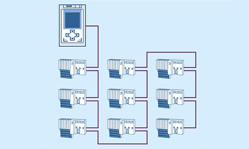 Example: Line topology in the PROFIBUS
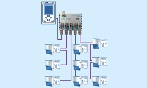 Example: Star topology in PROFIBUS with MULTIrep X5
Fundamental logical topologies can also be traced back to these three basic patterns:
The physical and logical basic topologies generally are not found in such pure structures in industrial networks, but rather blend into individual and complex shapes, depending on the structure of production plants, which are visualised on detailed topology plans. Every change on a plant can lead to a change of the network topology. That is why it is important that the corresponding topology plan is always kept up to date and available at any time for planners, repair technicians or service employees.
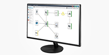
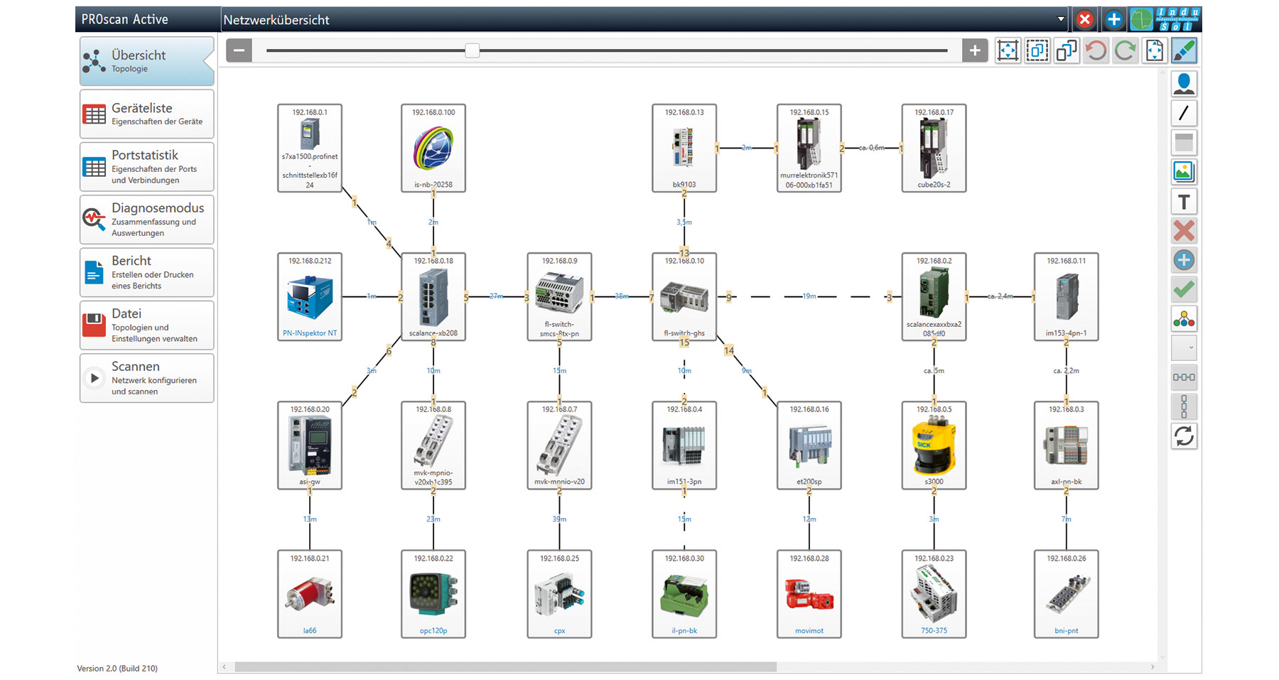 Example: Topology plan in PROscan® Active V2
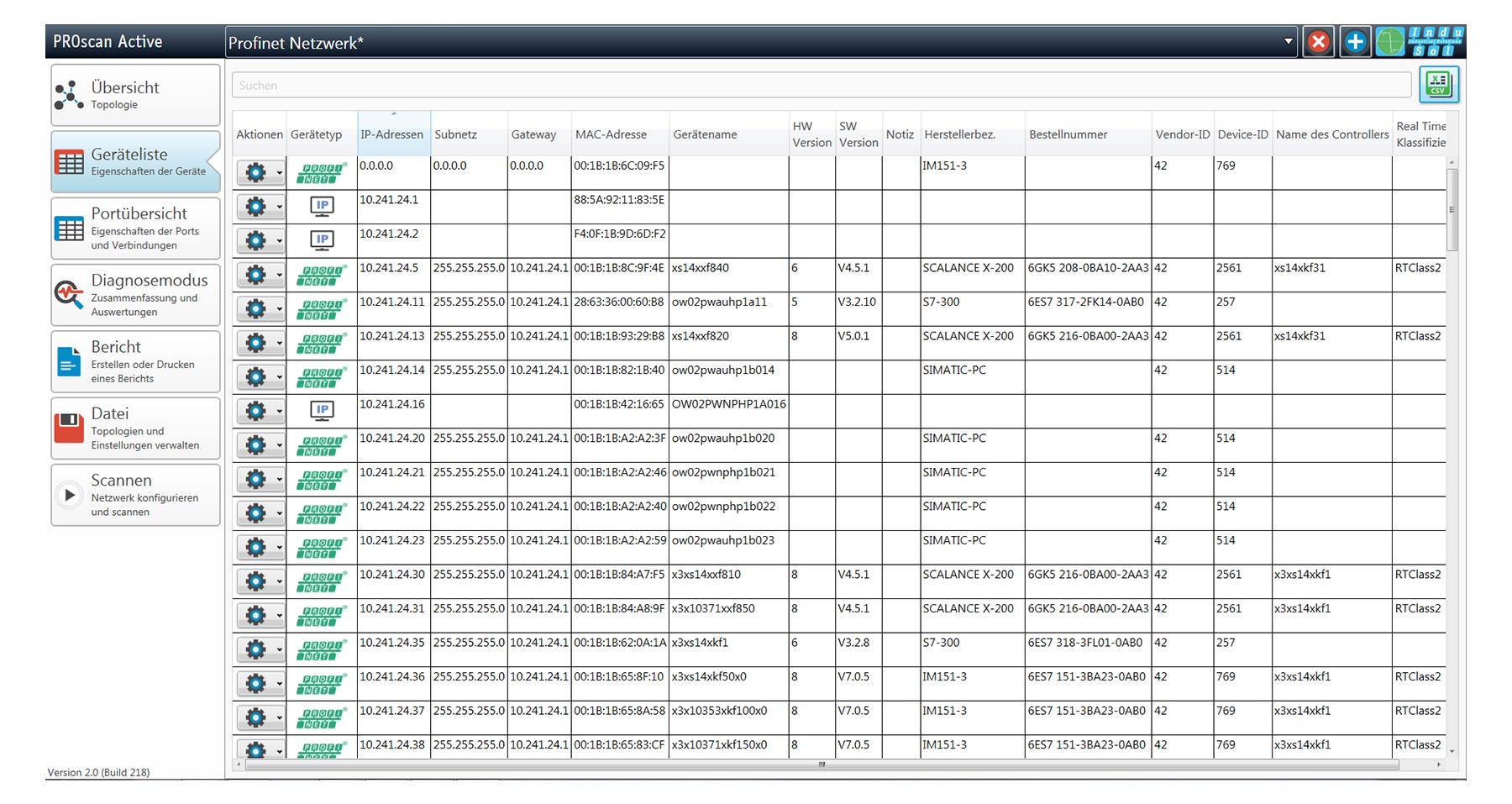 Example: Device list in PROscan® Active V2
Software tools greatly facilitate the work with topology plans. Using the circuitry/network planning software TOPOCAD you can document the topologies of existing PROFIBUS systems digitally or design topology plans for new systems. The network devices are placed on a freely-definable grid and are arranged and wired. For designing Ethernet-based networks, the network planning software PROnetplan is suitable with which you can optimise parameters such a network limit, payload, line depth and update rate. With that you create a realistic draft for a stable, nearly ideal network structure that you can submit to the installers as a graphic print-out with all values, a complete device list and important security information.
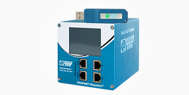
If you want to record the topology of a PROFINET or Ethernet network, we recommend the software PROscan® Active V2. With it you can determine all relevant device information, line information, port overviews and port statistics during running operations. Included in the prerequisites are manageable switches with SNMP functionality as well as network devices that make the PROFINET-specific parameters available. You can print out the scanned topology as a technical drawing or import it into the PROnetplan software in order to plan optimisations on an existing network there or to simulate a network structure. By this means, obligatory drafts for modernisation or expansions of the system can be made as well.
Stay informed! Receive the latest offers and news about industrial networks and their optimization - conveniently via e-mail.