Attenuation

J
ust as the yodelling of a mountain climber can barely be heard in the valley, electric signals can fade along long transmission paths or get lost. If you have ever laid out an antenna cable at home, you may know that the distance between the antenna socket and receiving device should not be too great. Cheap cables tend to lose the signal as of a length of ten to twenty metres. The reason for that is the attenuation, a physical value that is the difference between the inducted and received signal strength. It is specified in decibel (Db).
The attenuation (A) depends not only on the length of the transmission path, but also on the transmission frequency, the material of the transfer medium as well as the physical ambient conditions. The degree of the attenuation can be calculated for signal voltages (U) as well as for signal currents (I). The formulas are:
Since the values become logarithmic, please note that there are non-linear relations between them. Example: An attenuation of 6 dB can reduce the signal voltage by 50 %, whereas an attenuation of 0.5 dB reduces the signal voltage by only 11 percent. In order to make qualitative estimates using the attenuation dimension, the values need to be set in relation to the length of the transmission path. That is why the specification "decibel per length unit" is common.
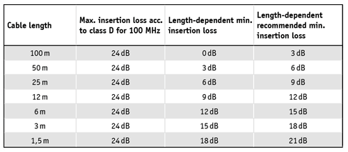 Line lengths and insertion loss in the PROFINET
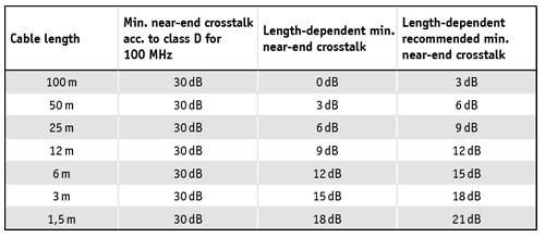 End crosstalk and line lengths in the PROFINET
In the international cable specifications of the International Standards Organization (ISO) and the European industrial standard (EN), the correlation between attenuation and length fades into the background to the benefit of the transmission frequency. Thus a maximum of 24 dB attenuation is specified at 100 MHz for twisted-pair cables of the category 5e – regardless of whether the line length is 1 m or 100 m. In practical application, it has shown that the fixed limit value tends to cause quality deficiencies to be neglected on shorter lines. That is why Indu-Sol recommends taking only length-dependent limit values into account for the qualitative evaluation of network cables.
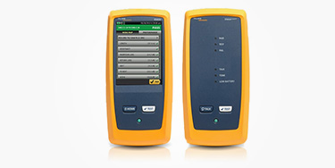
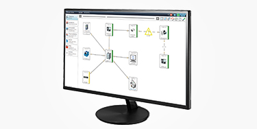
To check PROFINET and Ethernet network cables for their attenuation, it is best to use the ETHERtest V5 measuring device. With its help you can also instrumentally record and evaluate the resistance, the shielding, possible delays and the correct contacting. If you equip the device with additional adapters, it is also capable of carrying out attenuation and OTDR measurements of multi- and single-mode fibreglass cables. The recorded measurements are saved automatically by ETHERtest V5 and displayed graphically so that you can localise the source of the fault to within a decimetre. The supplied PC software compiles the measured values in the form of a measurement log.
Please note: On copper and optical fibres as they are employed by industrial communication networks, there are further effects next to the attenuation that must not be overlooked when evaluating the signal and transmission quality. These include return attenuation and cross talk.
Stay informed! Receive the latest offers and news about industrial networks and their optimization - conveniently via e-mail.