Meshed Equipotential
Bonding System (MESH-BN)

Impairments in industrial data communication may be caused by electromagnetic influences, even though the devices and components are OK. In order to prevent this, setup of a suitable equipotential bonding system is decisive in the planning phase already. According to common practice, installation often takes place in a star-shaped structure so far, so that all devices are connected to a few central earthing points. This keeps the number of paths on which the compensating currents can directly discharge low, leading to high stress on the earthing points.
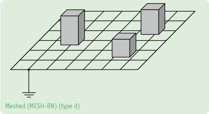
As use of higher-frequency power electronics increases in automated systems, stress on the devices additionally grows, requiring a new kind of equipotential bonding – the meshed equipotential bonding system (MESH-BN). Many short connections between the devices and all electrically conductive elements of the system create meshes that verifiably reduce the stress on the devices by distribution of the currents.
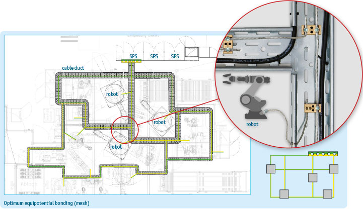
A MESH-BN (Meshed Bonding Network) is an equipotential bonding system with a mesh on a large area. The trunk forms an annular backbone of the system. An uninsulated 16 mm² conductor cable is usually used for this. The ring structure should not exceed a mesh width of 20 m in order to comply with the required impedance. The FE (function equipotential bonding) and BN (protection equipotential bonding; “bonding network”) connections of the electrical equipment are connected to the backbone of the equipotential bonding system with spurs at a length of 2 m, keeping distances as short and impedances as low as possible. This is done using conductor cables with a cross-section of 10 mm² (protection potential) and 6 mm² respectively (function potential). In addition to the electronic devices and robots, cable routes and ducts, tubes, and all electrically conductive parts of the system must be integrated EMC-compatibly. This is the only way to ensure maximal meshing of the system in order to provide as many paths to the current that are as short as possible.
Do you need any support?
We will gladly support you in proper implementation of a MESH-BN as a practice partner, developing an individual shielding and earthing concept together with you. On top of this, we can share theoretical and practical knowledge on EMC & equipotential bonding – on request directly at your plant on site.
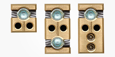
A narrow-meshed and low-impedance execution of the equipotential bonding system is required in machines and plants in accordance with DIN EN 50310. The conductor cables are attached locally in as many locations within the plant as possible, using the industry-capable EMClots® contact elements. The different builds are installed at a distance of approx. 1 m on cable routes, cross-beams, or other electrically conductive plant parts, permitting connection, attachment, and branching of conductor cables. The conductive setup of the connection terminals automatically integrate metal plant parts into the equipotential bonding system. The following functional builds are available:
Connection of the individual pieces of equipment takes place on short, low-impedance conduction paths, using highly flexible, tin-plated conductor cables. The fine-wired line structure provides sufficiently large surfaces for transmission of higher-frequency currents. The tin-plated coating contributes to reduction of the transmission resistance of the conductor cable and serves to protect against corrosion by aggressive media. Multifrequency conductor cables combine the properties of conventional conductor cables with those of a data cable shield. The inner core corresponds to the structure of a conductor cable with very fine wires. This is surrounded by a shield mesh that is similar to the shield of data lines. This conductor cable structure makes it possible to keep both low-frequency and higher-frequency currents away from the bus cables.
Other detailed and useful information can be found in the free EMClots®installation instructions. They can be downloaded from the EMClots® product page.
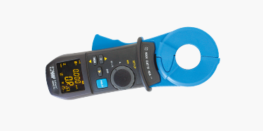
Proper equipotential bonding function is often assumed following installation of the conductor paths, without ever verifying correct function or performance of the system by measurements. Stable and reliable communication networks, however, are closely connected to the equipotential bonding system’s function. Higher-frequency currents often prefer the low-impedance shield of the data line rather than using the actually intended path via equipotential bonding. Measuring-technical evidence of good equipotential bonding in accordance with DIN EN 50310 and the associated verification of the admissible impedance values can be performed simply and intuitively using the mesh resistance amps clamp MWMZ II. A maximal impedance of 0.6 Ω is recommended for shield loop resistances; the impedance for equipotential bonding conductors should not exceed 0.3 Ω.
Do you have any questions or would you like advice from our experts? Simply send us your enquiry - conveniently online.