EMC guide values
for industry and automation

In order to ensure the functional safety of the automation network, the EMC acceptance check – based on measurements – is an essential quality certificate for systems. The objective is to ensure long-term trouble-free operation of all electronic devices in the network by means of targeted exclusion of disruptive factors from the PE/PA system. For this purpose, the ”status quo“ of EMC loads needs to be established by measurements, evaluated and documented. These measurements (EMC acceptance check) should take place under conditions that closely simulate production and after full completion of the automation technology according to planning specifications.
Measurements are required to determine the following quality parameters:
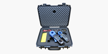
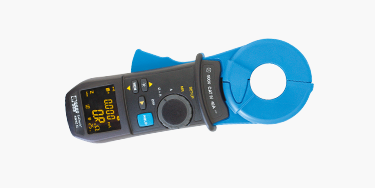
To carry out the measurements described above a measuring device is required that is capable of displaying a chronological sequence and preferably, a comparison of parallel measuring points.
In order to carry out these measurements the measuring device has tobe capable of displaying the quality of the existing bonding system in the kilohertz range as a minimum. From an economic point of view, it should be possible to perform the measurements during operation of the system.
The need for carrying out the measurements is related to frequent system downtimes that are not caused by communication errors in the industrial data communication but are rather caused by disturbances due to EMC interactions.
In addition to the described measuring tasks for capturing the status quo, it should also be possible to detect sporadic incidents. This requires the use of a measuring device both for temporary and permanent measurement in the sense of condition monitoring.
It is indisputable that the progressive development of power electronic components leads to an increase of interactions in the fieldbus-related environment. The widely publicised integration of the industrial office and production environment and the revolutionary networking of all data strings with each other are resulting in multiplied vulnerabilities to unwanted EMC interactions.
For this reason, the following reference or limit values should be observed during the required measurements:
| Protective conductor (PE) | max. 5 % of phase current |
| Protective bonding system | max. 300 mA (DGUV V3) |
| Functional bonding | max. 300 mA |
| Motor cable shielding | max. 300 mA |
| Signal cable shielding | max. 40 mA |
| Protective bonding system | max. 0.3 ohms at 2.2 kHz |
| Functional bonding | max. 0.3 ohms at 2.2 kHz |
| Motor cable shielding | max. 0.3 ohms at 2.2 kHz |
| Signal cable shielding | max. 0.6 ohms at 2.2 kHz |
The PE conductor should not be used as a conductive path for operating currents in normal operation. When a device is connected and the PE current, under normal operating conditions, is equal to or greater than 10 mA one of the following constructive measures has to be implemented:
The maximum current in the PE conductor must not exceed 5 % of the outer conductor current.
„Functional bonding is usually achieved by means of a connection with the PE conductor system (CBN). However, if the level of electrical disturbances in the PE conductor system is not sufficiently low so as to ensure the proper function of the electrical equipment, it may be necessary to connect the functional bonding system to a separate connector for functional grounding ...“
The question is left open what specific level of electrical disturbances is permissible or low enough for setting up a CBN. The Machinery Directive guideline does not provide a clear answer to this question.
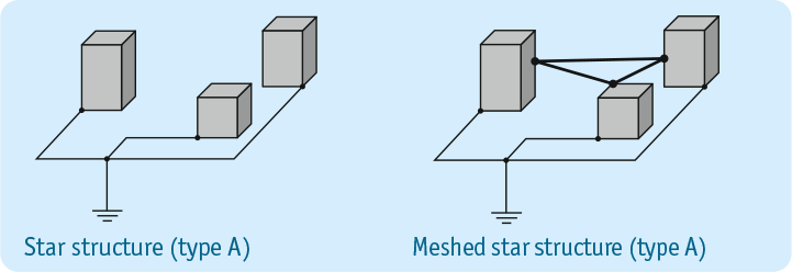
”This type of star-shaped network can be used in smaller installations such as homes, small commercial buildings, etc. and is generally acceptable for equipment that is not interconnected by signal cables or signal lines.“
This implies that equipotential bonding of the type A (EN 50310)with a star structure is not permissible for an electrical system. Electrical equipment is normally connected together by signal cables such as PROFIBUS or PROFINET. In this case, the improved type a (EN 50310) with ”meshed“ star structure is required.
Do you have any questions or would you like advice from our experts? Simply send us your enquiry - conveniently online.